A steam turbine governor is a component of the turbine control system that regulates rotational speed in response to changing load conditions. The governor output signal manipulates the position of a steam inlet valve or nozzles which in turn regulates the steam flow to the turbine. In this post, we’ll explore the functions of a steam turbine in detail.

Steam Turbine Governing

A well-designed steam turbine governor provides startup and on-line control for steam turbine driven generators and mechanical drives such as compressors and pumps. The core governor application must provide configurable options that enable flexible and scalable configuration to create multiple automatic starting modes (cold, warm, and hot) as well as manual operating modes such as slow rolling and trip and throttle valve testing.

Start-Up Speed Controller and Speed/Load Controller

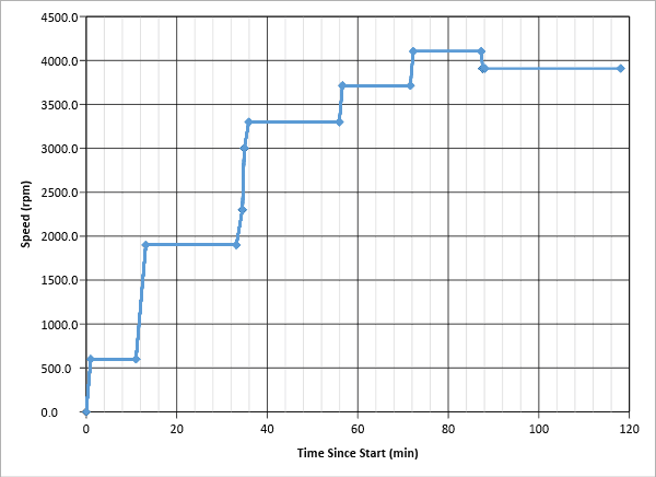
In a Petrotech provided system, the governor output signal to the steam inlet valve or nozzles is selected from two control modes, the Start-Up Speed Controller and the Speed/Load Controller. The Start-Up Speed Controller provides override control during the startup sequence for orderly ramping of the steam turbine through multiple warm up plateaus (STATES – refer to Figure 1). Once the unit reaches load speed (i.e., synchronous speed) the Start-Up Speed Controller continues to ramp until its maximum setpoint value (typically the maximum allowable speed configurable) is attained. During the starting and warmup sequence, the Start-Up Speed Controller manages the ramp rates from state to state, the speed at each state, and the dwell times of each speed plateau. Typically the ramp rates between the states are slow. This is necessary to avoid rapid and uneven expansion of the steam turbine components during the warmup period. In virtually all steam turbine systems there are operating speeds known as critical speeds which are determined during torsional and lateral analysis.

Critical speeds are operating regions where the rotational frequency nears the critical frequency and thus high vibrations occur. In these regions, the governor ramp rates are increased to provide more rapid acceleration through the critical band and thus minimize the level and duration of critical speed induced vibrations. Once the Start-Up Speed Controller brings the steam turbine to the load or rated speed, control is transitioned to the Speed/Load Controller.

Starting Curve Example
Figure 1 – Starting Curve Example

Generator Drive Application

In a generator drive application, the Speed/Load Controller receives its setpoint via the governor’s speed setpoint logic and provides three different controls modes, open-breaker Proportional-Integrator (P+I) control, closed generator breaker isochronous (island mode) Proportional-Integrator-Derivative (P+I+D) control, and closed generator breaker Droop Proportional (P) only control. If available, an additional utility tie breaker signal is used to indicate isochronous or droop mode.

In isochronous mode, the Speed/Load Controller regulates the generator’s rotational speed to maintain the appropriate 50 or 60 Hz frequency. As loads (motors, lights, etc.) are added or dropped off, the Speed/Load Controller changes the position of the steam inlet valve or nozzles to maintain the speed for the appropriate frequency.

In droop mode where the generator is connected to a utility grid the generator, once synchronized, will operate at the speed that matches the grid frequency. Since utility grids are infinite relative to the generator, the only way to add power to the grid is to effectively try to increase the frequency of the grid by increasing the speed setpoint to some level above the grid frequency. In many industrial plants where users generate their own power, the Speed/Load Controller will receive its setpoint from feedforward controllers such as steam pressure or flow controllers to regulate the consumption and thus the power added to the utility grid. If for some reason the steam supply begins to decline (boiler outage or other steam demand requirements), the feedforward controller will reduce the demand signal to the droop controller and thus reduce the power generated. Conversely, when the steam supply increases, the feedforward demand signal to the droop controller will increase, and additional power will be generated.

While in droop mode, and if the utility grid tie breaker opens, the Speed/Load Controller immediately transitions to isochronous mode and assumes speed-frequency control. Once the utility tie breaker is restored droop mode resumes.

Mechanical Drive Applications

In mechanical drive applications the Speed/Load Controller, like the droop controller, receives its setpoint from feedforward controllers such as steam pressure, steam flow, or process controllers. The process controllers will vary by application depending on the service required of the mechanical drive device. The primary difference between the droop controller and mechanical drive controller is that in the mechanical drive controller, the speed range is variable.

Extraction/Admission Governors

In many process plants there is a need to have steam available at varying pressures and temperatures for different process requirements. In these applications some steam turbines also have extraction ports upstream of the final steam turbine exhaust. The steam is extracted using an additional controller which is configured to maintain the extraction steam within a manufacturer defined set of limits known as an extraction map. The extraction governor is configured to regulate the extraction within the prescribed pressure and flow limits. An admission governor works similarly to admit steam to some intermediate port on the steam turbine.

Governors/Controllers for Steam Turbines

Our team can install control systems to ensure your steam turbine is protected and efficient, including the following:

  • Main Steam Valve Controls
  • Speed Override Controllers
  • Steam Inlet/Exit Pressure Controllers
  • Load Controllers
  • Steam Extraction/Admission Control
  • Extraction/Admission, Minimum/Maximum Override Controllers
  • Automatic Extraction/Admission Controllers
  • Extraction Valve Auto-Manual Stations

Reach Out to Our Team of Experts

No matter the type used, a governor protects your turbine by reducing its load or shutting it off completely in emergency situations, as well as providing more power in the case of high demands. At Petrotech, we have the control systems available to monitor, protect, and increase the efficiency of your turbomachinery system. Our integrated control systems provide complete or partial control system retrofits for steam turbine driven packages for compression, power generation, and pumping applications. These systems provide replacement and enhancement controls for outdated electro-hydraulic, analog-electronic, relay, and pneumatic based control equipment. To learn more about our line of turbomachinery controls, explore our literature library.

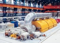
First photo courtesy of Siemens published on Wikimedia Commons.

Anti-Surge controllers use measurements from suction pressure and temperature, discharge pressure and temperature, and either suction or discharge flow, to determine the flow at which the condition of surge will occur. Within these controllers a surge limit is calibrated, initially from OEM provided data, and later from a field testing process known as surge testing.

A compressor undergoes surge testing to optimize the calibration of anti-surge control systems so that they fully protect a compressor from potentially damaging surge conditions while maximizing the compressor’s turndown (operating range). Surge testing can be done in the factory but most often it is done in the field after the compressor has been in service for quite some. The primary drivers to initiate a surge test are (1 the compressor is experiencing surge conditions before the flow reduces to the calibrated surge limit and 2) the compressor is prone to excessive recycling and there are indications that the calibrated surge limit is too conservative, thus preventing the operators from utilizing the compressor’s full turndown.

Anti-Surge Control systems operate by measuring the compressor’s operating pressure compensated flowrate and comparing it to the calibrated surge limit. Upon approaching this limit, a typical anti-surge controller will take action to decrease head pressure and increase flow, thus moving the compressor’s operating point away from the surge limit. Anti-surge control systems rely on data and will not perform optimally if these data are inaccurate. Once the compressor is installed in the field the factory determined surge limit can shift due to changes in the piping losses from the factory to the field. In addition, over time seal clearances, rotor fouling, and process gas changes can all contribute to surge limit deviations. Surge testing allows operators to determine the exact surge limit and enable them to optimally calibrate the anti-surge control system.

How Is Surge Testing Done?

Surge testing is an inherently high-stress event for both the compressor and the personnel involved and must be done with the safety of all participants and equipment in mind. Initially, engineers will develop a surge testing procedure establishing the methods to bring the compressor into surge, the methods and equipment necessary for measuring the relevant data (i.e., flow, temperature, and pressure), and the methods and procedures for minimizing the severity of the surge events.

The methods used to bring the compressor into surge vary, but they all involve reducing the flowrate through the compressor while increasing the pressure rise across the compressor. As mentioned earlier the surge limit is both flow and pressure based. Reducing the flowrate via pinching an inlet valve is an effective way to reduce the flow. However, since anti-surge controllers typically divert discharge flow back to the compressor’s inlet, it is imperative to know where the recycle line ties into the inlet. Pinching off a discharge block vale (i.e., dead heading) is another way to both reduce flowrate and increase pressure to induce a surge event. Once a surge event has been verified, the recorded data is archived, and the valve positions control systems setting are reset in order to restore the normal anti-surge protection.

Regardless of the methods used to induce a surge condition, during testing the flow should be decreased toward the surge limit very slowly and in incremental. As the compressor approaches its surge limit personnel shall preferentially observe and note oscillations in the flow measurement system. Often times the oscillations indicate incipient or light surge. At this point testing personnel can formally record the data and decide to reset the valve used to induce the surge. Stopping at this point prevents the occurrence of a deep surge event and reduces the risk of damaging the compressor and seals.

Since 1978, Petrotech has been providing flexible solutions for upstream, midstream, and downstream customers in the oil and gas industry, as well as power producers, marine engineers, and industrial automation users. We provide anti-surge compressor controllers along with a range of other custom-built, user-friendly systems backed by 24/7 support. Our mission is to help businesses increase efficiency, safety, and their bottom line. In addition to our cutting-edge equipment, we provide training programs tailored to the customer, including courses delivered on-site for a specific control system. For a more detailed technical discussion of our control systems, view our White Papers. If you are interested in seeing how our industry-leading solutions can benefit your business, contact us to request a quote today.

Although electricity was discovered as early as the 18th century, humans have made significant strides in producing electrical power through various means since that time. Among the most common means of producing energy is with turbines of different types, including gas and steam turbines. At the core of a turbine’s energy-producing operations is the spinning of its rotors. Here is a breakdown of how this spinning generates large quantities of electricity.

The Basics of Electrical Generation

Put simply, generators convert kinetic energy, which is based on movement, into electric energy. However, there are a number of different ways that this kinetic energy can be achieved. Most commonly, this electrical generation is created by using electromagnetic induction and by harnessing mechanical energy that causes a generator to rotate. Therefore, one of a generator’s most principal operations is the creation of kinetic energy.

How Gas Turbines Operate

Gas turbines, which are also known as combustion turbines, are composed of a gas compressor, a downstream turbine, and a combustion chamber known as the combustor. Air is drawn into the compressor where it meets with fuel, most commonly natural gas. This results in combustion, and the high-temperature and high-pressure gas then spins rotating blades, which draw more pressurized air into the combustor and spin the generator.

How Steam Turbines Operate

Operating on similar principles, steam turbines instead use extremely high temperature and highly pressurized steam to extract thermal energy. In the process, water is heated in a boiler to create steam, which is then pumped into the turbine to spin turbine blades. After, the steam is often cooled back into a liquid state and then used to create more steam. Much like in a gas turbine, the spinning generator is crucial to creating electricity.

How Spinning Creates Electricity

Today’s generators work on the same principles of electromagnetic induction that were discovered in 1832. In this year, a man named Michael Faraday discovered that electrical charges could be created when an electrical conductor was moved in a magnetic field. This movement resulted in a difference of voltages between the two ends of the wire or conductor, resulting in a flow of the electrical charge and finally an electrical current. In modern generators, the rotating elements are surrounded by a large magnet and coils of copper wire. The magnet is rotated as a result of the spinning wheels, and this results in a powerful stream of electrons, therefore converting the mechanical energy into electric energy.

The Efficiency of Turbines

As oil and gas are demanded more and more on a global scale, power production companies have been forced to consider the efficiency of turbines. Because of the many factors involved in energy production through turbines, there are a number of stages where efficiency is lost. Although the stage of spinning is where electricity itself is created, the preceding stages that require large amounts of heat and combustion can result in a loss of efficiency. In general, steam turbines are a more efficient model than gas turbines, because they require less in maintenance and equipment fees on average. Also, because they require a source of consistent heat, the operations generally involve a consistent heat source, resulting in higher efficiency. However, they also require a large amount of time to reach operating levels. The combustions involved in gas turbines mean that there is a significant fluctuation of temperatures, resulting in a loss of efficiency. However, many plants make up for this loss of efficiency by using a combined-cycle system. In this system, the hot exhaust gas from a gas turbine is transferred to a steam turbine, therefore greatly increasing the efficiency of the operations as a whole.

Because the spinning stage of turbine operation is so crucial to the creation of energy, it is important for power plants to have consistent control operations on their turbines, rotors, and facilities. For more information about how Petrotech provides intelligent control systems for power generation plants, explore our featured white papers.

According to a report by ResearchAndMarkets.com, the demand for oil & gas infrastructure is increasing demand for automation and control systems. They report the global crude oil & natural gas consumption grew by 1.2 percent and 2.24 percent annually during 2005-16. The production and resulting consumption numbers looked good for recent years, and they’re only expected to increase for the turbomachinery controls market as well. In a report by Market Research Engine, the turbine control system market is expected to exceed more than US$ 20 Billion by 2024. Let’s explore some of the potential factors for this growth.

Increased Production and Opportunities Across All of North America

It’s not just the U.S. where numbers are rising. North America as a whole is seeing positive numbers. Opportunities exist in the Western Provinces of Canada, where oil reserves are not controlled by national oil companies. Therefore, private sector investments in the turbomachinery control systems for upstream oil & gas market in North America will likely only increase. In a report by Mordor Intelligence, oil production in the United States is expected to increase even more due to surging production in the Permian Basin in West Texas, as well as in the Gulf of Mexico. The Permian Basin, though, is perhaps the most striking turn of events in the past three years.

A Boom in Midland Texas

Blanketing news outlets right now is coverage detailing the oil boom in a section of West Texas and East New Mexico known as the Permian Basin, a place where the oil boom effectively began in America, and a place where production has tripled in the past three years. According to numbers from the U.S. Energy Information Administration, oil production in the Permian reached 3.2 million barrels per day in May and continues to rise. This increase has created a situation in which production companies are even having trouble securing jobs for all of the needed work.

According to reporting by Vice, by some estimates, the nearby city of Midland currently lists 20,000 unfilled positions. The workers that come to the basin show up to fill a variety of upstream-related positions, from roughnecks to chemical engineers. They’re being welcomed with six-figure positions after appropriate training is undergone, if necessary. Since a large amount of the oil found in the basin is attained via hydraulic fracking, which requires sand and chemicals to be forced into the shale formation to release the oil and natural gas, even companies that provide the sand for the fracking can be seen lining the highways of nearby towns like Midland and Odessa with dozens of big rigs. It’s yet to be seen if the Permian Basin will rival the production of massive fields like the Ghawar Field in Saudi Arabia or deepwater drilling in the North Sea. However, some corporate entities are already capitalizing on what could be a major producer for years to come—Exxon Mobil bought about 1.8 million acres of field in the Permian, equating to roughly the size of Delaware. But, with the increase in production comes an increase for smarter control systems that can improve efficiency and better monitor efforts in the production and refining sectors.

Increased Production Necessitates More Efficient Controls

Increasing competitive pressures in the production industry have driven dramatic changes in the operational needs of oil rigs, process plants, utilities, and pipelines. Industries need to be able to start production quickly, increase their cycles while in operation, and get the most out of their assets by having control systems that make sure their production stays in operation without fail. With these sudden increases, some sectors are struggling with the strain that’s being put upon the midstream pipeline sector.

As mentioned previously, companies can’t find enough manpower to move the amount of oil coming up, but there’s also the logistics issue of dealing with natural gas by-products associated with hydraulic fracking. Producers can only flare (burn off) so much associated gas due to regulations, so it’s yet to be seen what pipeline solution will present itself for the natural gas by-products associated with the oil coming out of the Permian Basin. Colton Bean, director of midstream research at Tudor Pickering Holt & Co., emphasized that this problem could become costly for oil producers: “The ultimate downside scenario is you have to effectively slow down on your oil production because you can’t evacuate gas from the basin.” Regardless, oil & gas production companies need control systems that can help streamline their operation while keeping their workers safe.

Work With a Leader in the Control System Industry

Since 1978, Petrotech has been providing flexible solutions for upstream, midstream, and downstream customers in the oil and gas industry. We can help you improve your unit’s stability and responsiveness, operate closer to the control limits, increase production, and prevent loss. We provide advanced compressor control systems, gas and steam turbine control systems, and a range of other custom-built, user-friendly systems backed by 24/7 support. In addition to our cutting-edge equipment, we provide training programs tailored to the customer, including courses delivered on-site for a specific control system. For a more detailed technical discussion of our control systems, view our White Papers. If you are interested in seeing how our industry-leading solutions can benefit your business, contact us to request a quote today.