
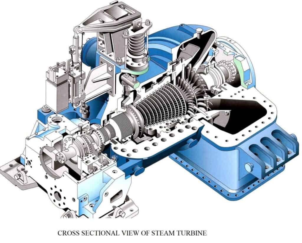
Steam turbines serve as integral components in the petrochemical, power generation, and refinery industries. The foundational architecture of a steam turbine comprises a rotor, precision-supported by bearings and encased within a cylindrical casing. The controlled interaction between steam and meticulously designed blades results in a tangential force and instigates the systematic rotation of the rotor. This intricate arrangement visualizes a steam turbine as a series of windmill-like structures on a single shaft.
Parts of Steam Turbine
Steam Chest and the Casing
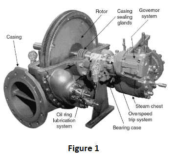
The steam chest connects to the high-pressure steam supply line while the low-pressure steam exhaust line affixes to the casing as shown in Figure 1. The steam chest positions between the casing houses the governor valve and the overspeed trip valve. The nozzles, located inside the casing, direct the flow of steam onto the rotating buckets.
Rotor
The rotor consists of a bucket-equipped shaft and disc sections. The shaft emerges from the casing and through the bearing cases. A driven pump connects to one end of the shaft and the speed governor and overspeed trip system are located on the opposite end.
The Bearing Cases
As shown in Figure 1, the bearing cases support the rotor, along with the assembly steam chest and steam chest. The bearing cases contain journal bearings and rotating oil seals. The oil seals keep oil inside and water, dust, and steam out. The steam end bearing case also includes the rotor positioning bearing and the rotating parts of the overspeed trip system. The steam end-bearing case covers the moving parts.
Casing Sealing Glands
A seal exists between the casing and the shaft provided by the casing sealing glands. For this, the system uses spring-backed, segmented carbon rings. These rings are supplemented by adding a spring-backed labyrinth section that makes the exhaust steam work better.
Governor System
Control systems, called governor systems are built into steam turbines and can sense when the speed changes. They can change turbine speed by changing the governor valve, which controls the steam flow through the turbine. The governor also contains rotating weights that push against each other by a servo motor system. The governor determines the turbine shaft’s speed via a straight link, or a magnetic impulse from a gear. A set point compares the rotor speed and the servo motor receives the governor output signal. Changes in the input and exit steam of the turbine, as well as changes in how much power the pump needs, will dictate the turbine’s speed. When the speed changes, the governor weights move, which moves the governor valve.
Over-Speed Trip System
The governor takes control of the rotating system, swiftly sealing the trip aperture to interrupt the flow of steam to the engine upon detecting an excessive speed. This arrangement comprises of a turbine shaft collar featuring a pin or weight under spring tension, an expeditious closure valve distinct from the governor valve, and an interconnecting linkage. As the pin rotates within the turbine shaft, it generates a centrifugal force surpassing the spring’s opposition at a specific velocity.
Labyrinth Seal
A labyrinth is a structure that is meant to keep fluid from going from a high-pressure zone to a low-pressure zone by letting only a small amount of fluid leak out. Maintaining the smallest possible clearance between the labyrinth and the shaft is important.
Nozzle Ring and Curtis Stage
Assembly of the nozzle ring and reversing blade in the steam end casing is a meticulous process. The nozzle ring firmly secures to the lower section of the steam end casing through bolts.
The nozzle ring interfaces with what is called a Curtis stage. This Curtis stage provides an essential part of the turbine’s design, especially in turbines with a significant drop in steam pressure.
A Curtis stage typically consists of one or two sets of highly specialized blades that typically undergo a specialized heat-treating process to directionally align the grains. After the blades, exists a set of stationary nozzles or guide vanes. The high-pressure steam first passes through the stationary nozzles, where it expands rapidly, converting the thermal energy of the steam into kinetic energy. This high-velocity steam then strikes the moving blades, imparting momentum and thus rotating the turbine shaft.
The reversing blade system strategically lies inside the Curtis stage, housing two rows of blades. Acting as conduits, the nozzles embedded in the nozzle ring propel the steam from the steam box to the initial row of blades in the Curtis stage, held securely by the nozzle ring. Once the steam traverses the first row of blades and progresses towards the subsequent blades, the reversing blades help alter the flow direction. The entire unit stabilizes along its length by spacers, reducing vibration and ensuring a smooth-running turbine.
Sentinel Valve
This part is at the top of the exhaust end of the turbine casing and acts as a warning system. It activates when the pressure inside the turbine’s exhaust end casing becomes too high. When the pressure inside the casing rises above a certain level and exceeds the standard working pressure, the valve will release a small quantity of steam that can be seen and heard.
Auxiliary Steam Valves
Auxiliary valves improve working efficiency when there are changes in load or steam conditions. The valves are inside the steam tunnel, between the steam chest and the nozzle ring at the lower end of the turbine casing’s steam end. The tube splits into three separate sections. One section stays open all the time so that steam can keep going to a bank of nozzles in the nozzle ring. The other two sections contain auxiliary hand valves to control steam flow to two other banks of nozzles within the same nozzle ring.
Turning Gears
Large turbines come with gears that rotate to make it easier for the rotors to turn slowly while they warm up and cool down. To keep the shaft or rotor straight and balanced, this is done to ensure consistent temperature around its entire diameter.
Carbon Ring Seals
The structure is made up of pieces of a carbon ring that are held together by a spring. The anti-rotation stops fit firmly into the notches in the bottom half of the interstage casing. In addition, the carbon rings are used to successfully stop any rotation from happening.
Turbine Cylinders
Turbine cylinders have to withstand the pressure of the steam, so they need to be built solidly with thick walls. Because they are exposed to high steam temperatures, thick-walled components are not desirable. When temperature differences exist inside stiff parts, they put a lot of stress on the material. These stresses can break down materials when added to the mechanical stress that comes from pressure.
Petrotech’s Steam Turbine Control Support
Petrotech’s advanced steam turbine controls for compressor and generator drive applications feature an integrated control package that provides speed and capacity control. Overspeed protection is implemented in both the software and hardware. To learn more about our line of turbomachinery controls, explore our literature library.