
A steam turbine governor is a component of the turbine control system that regulates rotational speed in response to changing load conditions. The governor output signal manipulates the position of a steam inlet valve or nozzles which in turn regulates the steam flow to the turbine. This post explores the function of a steam turbine governor including other vital information like speed control and generator drive.
What is the Function of a Steam Turbine Governor
A well-designed steam turbine governor provides startup and on-line control for steam turbine driven generators and mechanical drives. Some examples of these include compressors and pumps. The core governor application must provide configurable options that enable flexible and scalable configuration to create multiple automatic starting modes. For example, cold, warm, and hot starting modes. In addition, the governor must be able to provide same for manual operating modes such as slow rolling and trip and throttle valve testing.
Start-Up Speed Controller and Speed/Load Controller
In Petrotech’s control systems, the governor output signal to the steam inlet valve or nozzles is selected from two control modes. These modes are the Start-Up Speed Controller and the Speed/Load Controller. The Start-Up Speed Controller provides override control during the startup sequence for orderly ramping of the steam turbine through multiple warm up plateaus (STATES – refer to Figure 1). Once the unit reaches load speed (i.e., synchronous speed) the Start-Up Speed Controller continues to ramp until its maximum setpoint value (typically the maximum allowable speed configurable) is attained.
During the starting and warmup sequence, the Start-Up Speed Controller manages the ramp rates from state to state, the speed at each state, and the dwell times of each speed plateau. Typically the ramp rates between the states are slow. This is necessary to avoid rapid and uneven expansion of the steam turbine components during the warmup period. In virtually all steam turbine systems there are operating speeds known as critical speeds which are determined during torsional and lateral analysis.
Critical speeds are operating regions where the rotational frequency nears the critical frequency, thus, high vibrations occur. In these regions, the governor ramp rates are increased to provide more rapid acceleration through the critical band. Therefore, minimizing the level and duration of critical speed induced vibrations. Once the Start-Up Speed Controller brings the steam turbine to the load or rated speed, control is transitioned to the Speed/Load Controller.

Generator Drive Application
In a generator drive application, the Speed/Load Controller receives its setpoint via the governor’s speed setpoint logic. It also provides three different controls modes, open-breaker Proportional-Integrator (P+I) control, closed generator breaker isochronous (island mode) Proportional-Integrator-Derivative (P+I+D) control, and closed generator breaker Droop Proportional (P) only control. If available, an additional utility tie breaker signal serves to indicate isochronous or droop mode.
Isochronous Mode
In isochronous mode, the Speed/Load Controller ensures the generator operates at a steady 50 or 60 Hz frequency. As electrical loads like motors and lighting systems connect or disconnect, the controller adjusts the steam inlet valve or nozzles to maintain the correct speed. This real-time adjustment keeps the generator running at a stable frequency, ensuring consistent power delivery.
Droop Mode
In droop mode, the generator synchronizes with the utility grid and operates at the grid’s frequency. Since the grid is significantly larger than the generator, the system cannot directly alter its frequency. Instead, increasing the speed setpoint slightly above the grid frequency allows the generator to contribute power.
In industrial plants where operators generate their own electricity, the Speed/Load Controller receives its setpoint from feedforward controllers. These controllers regulate parameters like steam pressure or steam flow to determine the appropriate power output. When steam availability decreases due to a boiler outage or increased steam demand, the feedforward controller reduces the droop controller’s demand signal, lowering power generation. Conversely, an increase in steam supply raises the demand signal, leading to greater power output.
If the utility grid tie breaker opens while in droop mode, the Speed/Load Controller instantly switches to isochronous mode and assumes direct speed-frequency control. Once the tie breaker is restored, the system seamlessly returns to droop mode.
Mechanical Drive Applications
In mechanical drive applications, the Speed/Load Controller operates similarly to the droop controller but with a variable speed range. Instead of a fixed grid frequency, the setpoint comes from feedforward controllers that manage steam pressure, steam flow, or process-specific requirements. The control strategy depends on the application and the mechanical drive’s operational needs.
Extraction/Admission Governors
Many process plants require steam at specific pressures and temperatures for different industrial operations. Some steam turbines feature extraction ports located upstream of the final turbine exhaust. These ports allow controlled steam extraction, ensuring the process receives steam within defined pressure and flow limits.
An extraction governor regulates this process, maintaining steam output within a manufacturer-defined extraction map. Similarly, an admission governor controls the intake of steam into intermediate turbine ports, ensuring process stability and efficiency.
Governors/Controllers for Steam Turbines
Our team can install control systems to ensure your steam turbine is protected and efficient, including the following:
- Main Steam Valve Controls
- Speed Override Controllers
- Steam Inlet/Exit Pressure Controllers
- Load Controllers
- Steam Extraction/Admission Control
- Extraction/Admission, Minimum/Maximum Override Controllers
- Automatic Extraction/Admission Controllers
- Extraction Valve Auto-Manual Stations
Reach Out to Our Team of Experts
Regardless of the steam turbine governor type, its primary function is to protect the turbine, adjust power output, and respond to fluctuating demands. At Petrotech, we offer integrated control solutions that monitor, safeguard, and improve steam turbine efficiency. Our systems provide full or partial control retrofits, replacing outdated electro-hydraulic, analog-electronic, relay-based, and pneumatic control equipment.
With proven technology and decades of expertise, Petrotech delivers state-of-the-art control systems for steam turbines in compression, power generation, and pumping applications. To learn more about our advanced turbomachinery controls, explore our whitepapers or contact our experts today.
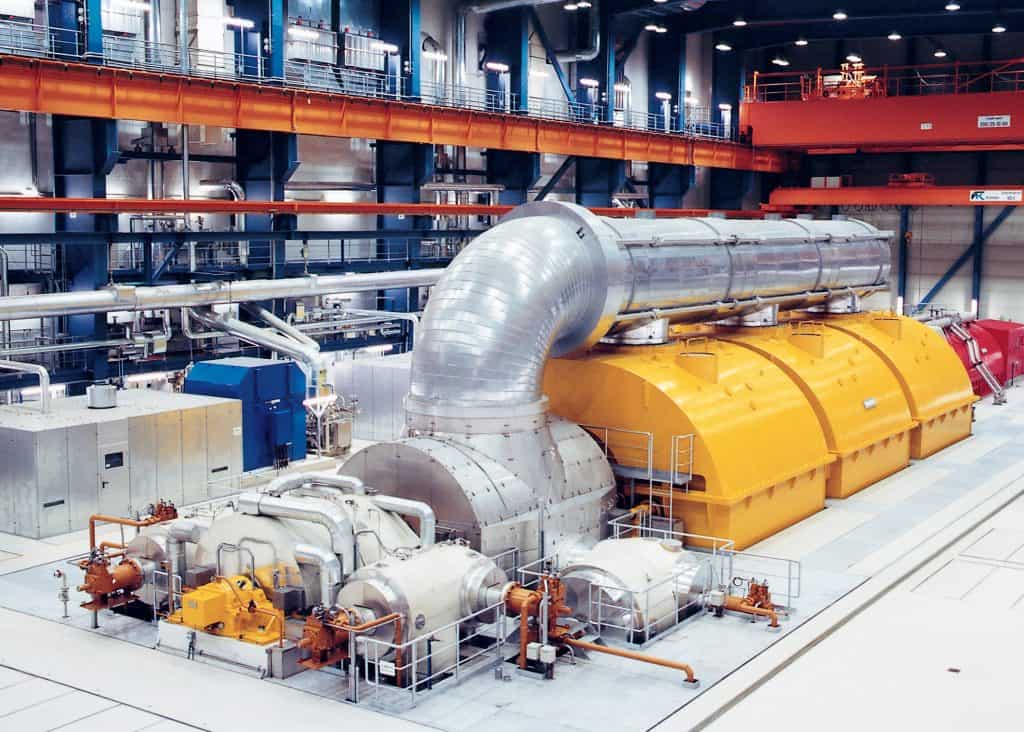
First photo courtesy of Siemens published on Wikimedia Commons.