
NOx Emissions: The Petrotech Solution to New York’s Limits
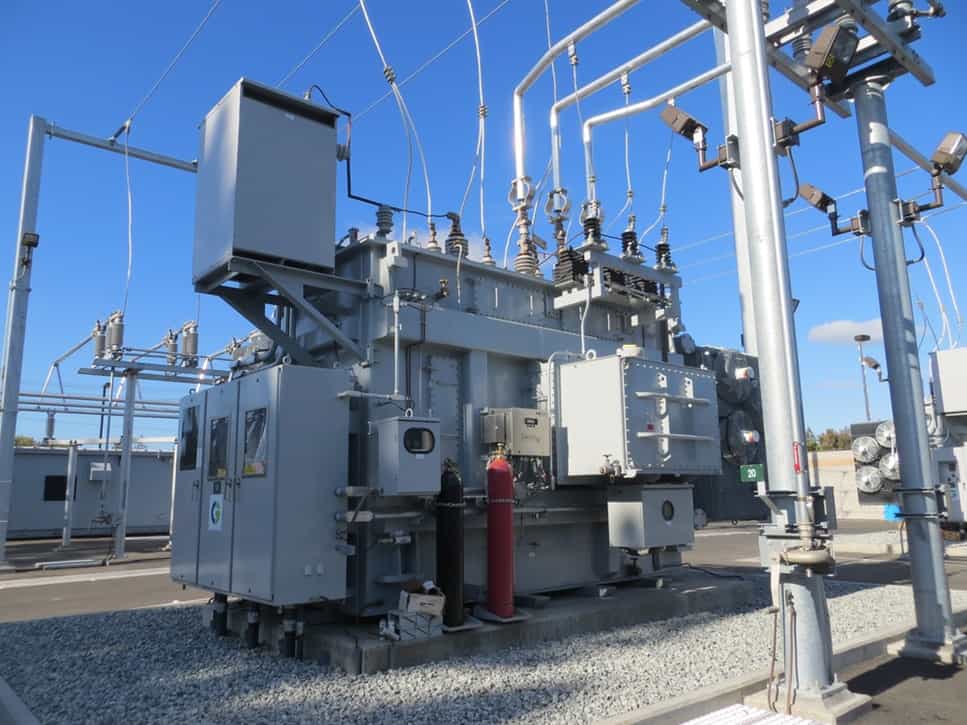
As a leader in advanced technology and turnkey solutions, Petrotech has the right solution to New York’s NOx emissions limits legislation.

As a leader in advanced technology and turnkey solutions, Petrotech has the right solution to New York’s NOx emissions limits legislation.

This article reviews what open architecture control systems are, IEC 61131 development, its programming languages, as well as their benefits.
The main difference between droop and isochronous control modes lies in their relationship to frequency. This article explains the differences between isochronous and droop control modes, and when it is ideal to deploy either of them.
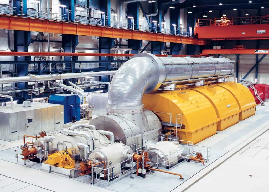
This article reviews the purpose of turbomachinery controls, typical elements of the system, trends, innovations, and single vendor benefits.
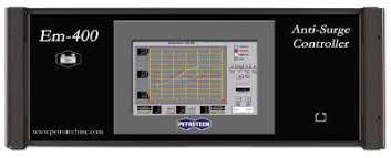
Plant operators shouldn’t have to continually monitor or adjust their compression system to maintain optimum air mass flowrates. If a

This article reviews what reciprocating engines are, how they work, advantages, as well as maintenance requirements.

This article reviews how to select the right steam turbine oil for an application, and how to operate efficiently under demanding conditions.
This post explores the function of a steam turbine governor including other vital information like speed control and generator drive.
This article explains how does surge testing work, and how it helps optimize compressor performance while maximizing operational efficiency.
This article reviews how the spinning of turbines helps them to generate power, and factors influencing the efficiency of turbines.