Although there is variation from facility to facility, the layout of gas turbine power plants plays an important role in the operations of the power plant. Here is a breakdown of common power plant layouts and how they affect the efficiency of the plant.

How Gas Turbine Plants Operate

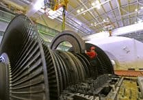
The particular operations of a gas turbine power plant influence the layout of an operational site. Gas turbines are combustion engines that use natural gas or other liquid sources of energy to create mechanical energy. The mechanical energy is then used to produce electrical energy with a generator. Gas turbines are composed of the following three major parts:

  • The compressor, which uses pressurized air to rotate blades in the turbine
  • The combustor, which heats gasses to temperatures as high as 1400-1500 degrees Celcius
  • The turbine, which is composed of blades which rapidly rotate and create mechanical energy.

Gas turbine power plants have one of the highest rates of efficiency when it comes to converting fossil fuels into electrical power, and can offer shorter gestation times compared to other types of facilities.

Common Layout for Power Plants

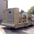
Because of the interconnecting of air, gas, and other circuits, the layout of a gas turbine power plant must be carefully considered in order to minimize waste and inefficiency. In general, accommodations for the turbine housing take up the majority of the space in a plant, with the auxiliaries being the main building. However, fuel oil storage tanks are generally placed adjoining the turbine housing, with intercoolers, combustion chambers, waste heat boilers, heat exchangers, and the sometimes complicated ductwork taking up the rest of the building.

Selecting a Gas Turbine Power Plant Site

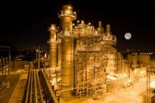
Before the layout of a gas turbine power plant can be designed, the proper site for the plant must be selected. There are a number of variables that go into this decision, as certain factors may make the plant less efficient or more costly. The site should be as close as possible to the load center to minimize transmission costs. Land should be relatively cheap as gas turbines can take up a significant area, and also so that the plant and facility can be expanded if necessary. It should be in a location relatively far from populated areas due to the noise of the operation, but there should be easy transportation for workers as well. Finally, plants should be built in locations where fuel is available for a reasonable rate, and where the land has a high bearing capacity, as the plant’s vibrations and other operations will create a significant load.

Advantages of Gas Turbine Power Plants

Gas turbine power plants can offer a relatively compact and cost-efficient means of producing energy from fossil fuels. Because gas turbines do not require boilers or feed water arrangements, they are generally smaller than steam turbine plants of the same capacity. They are also generally simpler in design for these reasons. Gas turbine power plants can also require smaller maintenance charges, as well as initial and operating costs that are lower than those of steam power stations. Unlike other power plant systems, gas turbine power plants can also be started in cold weather conditions.

Disadvantages of Gas Turbine Power Plants

Although gas turbine power plants are more compact, steam power plants often have longer lifespans. This is because the high temperature of the combustion chamber (3000° F) can reduce the lifespan of the plant. Because exhaust gases from gas turbine power plants contain sufficient heat, the efficiency of the plants may be as low as 20 percent.

To maximize the efficiency of a gas turbine power plant, the layout must be taken into consideration. However, it is equally important to ensure that the controls of a plant are ensuring it operates safely and at full capacity. For more information about maximizing the efficiency of your plant with the most up to date control systems, reach out to our team today by requesting a quote online or by calling Petrotech at 504-620-6600.

Steam turbines are efficient but complex machines, meaning that there are a number of possible ways they may malfunction. One such malfunction is known as vibration, which occurs as a result of impacts between stationary and rotating parts. Although there are a number of solutions for vibration, early detection through technical consultations is key to maintaining proper efficiency and preventing possible damage to the machine.

How Steam Turbines Work

Steam turbines are powered by steam, meaning the first step is to heat water to an extremely high temperature. Generally, the water is heated by a fossil fuel, solar heat, or another type of renewable energy. Then, the steam from the boiler is pumped into the steam turbine, rapidly turning the turbine blades and resulting in mechanical or rotational energy. After, the steam is passed into a cooling tower or cooled naturally using a lake or river. Some steam will be converted back into water to create the process again. Steam turbines have a wide range of uses, but they are often used as mechanical drives for pumps, compressors, and generators.

The Root of the Problem of Vibration

The problem of vibration is generally originated when rotors in the turbines bend. This bending often occurs during some of the turbine’s operational evolutions, leading to vibration or even system failure down the line. However, the resulting vibration is not the problem itself, but rather a symptom of system-wide flaws. In fact, rotor bending is one of the most serious problems that power plants face, as they can limit generation as well as cause the plant to spend more money and time on operation and maintenance costs.

The Cause of Vibration

During operation, steam turbine rotors are expected to bend, to an extent. There should be a system of bearings and supports put in place to keep the static and dynamic forces within expected and controlled range. This often results in what is known as cascading impacts, meaning it begins an unavoidable chain of events that negatively affect the system. In this case, it results in vibration, inefficiency, and the need for technical consultations and possibly maintenance down the line.

Other Effects of Rotor Bending

Insufficient clearances in the labyrinth or diaphragm of a system often result in rubbing, which can have a number of negative effects on the turbine, including vibration. In addition to vibration, rubbing can disrupt the end sealing of the rotor. Contact between a rotor operating at high speeds and a stationary surface not only leads to damage but also creates localized temperature increases where contact is made, raising the temperature of the metals because of friction. Additionally, this rubbing can create elastic deformations on the rotors themselves, leading to a further increase in vibration levels. In a 3,000-rpm turbine, bending is permissible up to 0.02-0.03 mm in any given section, but the limit is 0.05 mm on turning gearing. If bending exceeds these limits, it could result in permanent deformation of some components of the turbine.

Uneven Cooling and Warming

Uneven cooling and warming of rotors can also increase vibration in the unit. Uneven cooling can cause the rotor to contact stationary surfaces, meaning that a high-temperature rotor could bend due to its mass if it is left to cool in a stationary position. Uneven warming can result in shaft bending for similar reasons: rotor contact with stationary parts, increased temperatures, and more bending.

Although steam turbine vibrations are not the problem itself, they are a symptom that indicates complications in a turbine that should be addressed quickly to avoid permanent damage. For more information about the operations of steam turbines and Petrotech control systems that keep them functioning smoothly, visit our literature library or give us a call at (504) 620-6600 today.

Anti-surge controllers are found on centrifugal compressors. The basic function of anti-surge control is to maintain a minimum flow during extreme conditions. Using measurements from suction and discharge pressure, discharge pressure and temperature, and either suction or discharge flow, the anti-surge controller determines the flow at which the condition of surge will occur.

Anti-surge Controller Setpoint

To compensate for measurement inaccuracies, the logic solver adds a control safety margin (typically 10 percent) surge flow, which is then used as the anti-surge controller setpoint. This setpoint is the minimum flow that will be allowed through the compressor. In order to maintain the flow at or above the anti-surge controller setpoint, the logic solver uses a Proportional-Integral (PI) control loop to generate an output signal, which is directed to a recycle control valve. The recycle control valve is connected to both the suction and discharge flow lines on the centrifugal compressor. During low flow conditions, anti-surge control output signal actuates (opens) the recycle control valve to divert discharge flow back to the suction in order to maintain the minimum flow setpoint.

Anti-surge Controller Vs. General Process Flow Controller

What differentiates an anti-surge controller from a general process flow controller is that the minimum flow setpoint is dynamic and continuously changes as the process gas conditions (pressure and temperature) and process gas properties (molecular weight) change during operation. Modern-day anti-surge control logic solvers utilize process gas condition and process gas property invariant techniques to dynamically determine the minimum flow setpoint.

Advanced compressor control solutions from Petrotech are flexible, cost-effective, and offer protection capabilities for your system. For an overview of our control systems and how we can update your equipment, visit our literature library to download our white papers on our control systems.

With a perpetually increasing population putting a higher global demand on the oil and gas industries, power production companies are faced with the challenge of increasing production while minimizing waste. Throw into the mix volatile market prices and constantly changing regulations, and it can seem like an uphill battle for plant managers to create an efficient production model. However, there are some key ways that stakeholders can get the most of their gas or steam turbines so that they can deliver sufficient production levels at a lower cost.

Gas and Steam Turbines: Which Is More Efficient?

While both types of turbines have their advantages, typically, steam turbines are more efficient models than their gas alternative. This is mainly due to steam turbines being able to produce more energy output while costing less in maintenance and equipment fees. Steam turbines rely on a stable source of external heat, and in doing so, their kinetic energy transference is able to maintain a consistent heat source, albeit losing some heat and energy in the process. One downside to steam turbines is the excessive amount of time they take to reach operating levels.

Gas turbines, however, rely on a combustion of gases that can have fluctuations in temperatures. A gas turbine uses a high energy fuel that is burned in the combustion chamber with compressed air (and because of that compression, that air gets very hot). As such, inefficiencies in other aspects can be found—specialty turbine blades that need to withstand the high temperatures and exhaust heat boilers required for the exhaust heat. However, by transferring this hot exhaust gas from a gas turbine to a steam turbine, many power production plants are finding even more efficiency through a combined-cycle system.

Combined-cycle Power Plants Are Showing Very Efficient Numbers

According to a report by the U.S. Energy Information Administration, the average gas-fired combined-cycle plant operated for the equivalent of 4,932 hours at full power in 2015, up from 4,489 hours in 2012, an increase of almost 10 percent. For comparison, the average coal unit operation dropped to the equivalent of 4,783 hours from 4,981 hours over the same period.

As the name implies, a combined-cycle power production plant uses both gas and steam turbines to drive generation sets. A combined-cycle power plant produces its main source of energy from a generator connected to a gas turbine. But, it also takes the excess hot exhaust gases from a gas turbine, purifies and uses that exhaust to produce steam, and then uses that steam in a steam turbine connected to a generator to produce even more energy. There have already been some remarkable results so far.

Records Set at a GE Combined-cycle Plant

In 2016, GE manufactured a combined-cycle power plant in France with an efficiency of 62.22 percent. It was so efficient that it made it into the Guinness Book of World Records. According to GE, “The airflow through the 605-MW Bouchain plant’s HA compressor could fill the Goodyear blimp in 10 seconds. The tip of the last blade in the 9HA.01 is said to move at 1,200 miles per hour—one and a half times the speed of sound.” And, because the model is rooted in a gas turbine, the plant can respond to energy demands very quickly, being capable of reaching full power in less than 30 minutes, a valuable benefit to have when extreme weather or unexpected events require on-demand power.

One of the significant benefits of combined-cycle power plants is their ability to reduce emissions by harnessing the exhaust gas from a gas turbine and utilizing it. In GE’s combined plant, they replaced a coal plant that was previously on site. They were able to reduce site CO2 emissions by 65%, SOx emissions by 95%, and cut particulate emissions to zero.

Utilizing the benefits of both gas and steam turbines just may be the direction that plants will be heading toward in the near future.

It’s All About Efficiency

At Petrotech, we seek efficiency in every aspect of our business model. It’s our goal to make sure your business can increase productivity while eliminating operations waste. Our rotating machinery control systems for gas, hydro and steam turbines, generators, reciprocating/diesel engines, reciprocating compressors, centrifugal and axial compressors, pumps and all associated ancillary systems help companies in the energy sector worldwide do just that. Whether you’re seeking an upgrade or a new install, we can make sure you have the flexible, open, and integrated control system in place that ensures you meet productivity levels. We’ve installed thousands of systems worldwide. To get started on your project, request a quote with us today.